Unexpected changes in the power supply may become the cause of many problems in the homes, offices, and industries.Voltage up and down in the electric power has a very dangerous effect on the connected load.Fluctuations of overvoltage and undervoltage protection systems are produced to control the bad effects. Generally, these systems are used in water pumps, agriculture motors, etc. We are going to discuss the different control structures, like timers and compactors, of the undervoltage & overvoltage protection system in this article.
What are overvoltages and undervoltages?
When the voltages in any circuit exceed its upper limit, it is called overvoltage, and when the voltages decrease from its lower limit, it is called undervoltage. Depending on the duration, the over-voltage duration is like a transient, voltage spike, and power surge. The graph given below shows the variations between the time and voltage in both over-volt and under-volt variations.
Circuit Using Comparator
This circuit is used to trip the mechanism to protect it from damage. Generally, in homes and industries, we observe that there is a frequent change in AC power. Due to these changes in the AC power, the electronic circuits may be damaged easily. To avoid this problem, we implement the tripping mechanism of over-undervoltage protection.
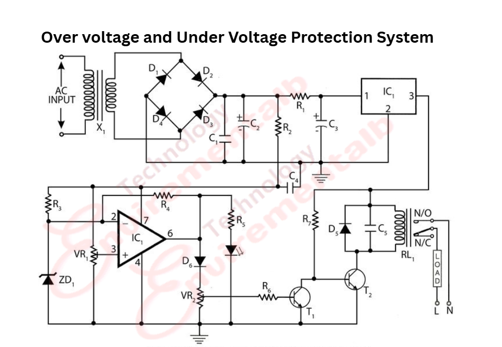
Components Needed
- 12-volt transformer
- IN 4007 (D1, D2)
- 1k (R1, R2)
- 5k pot (P1, P2)
- BC 547 Transistors (T1, T2)
- 12V relay (RL1)
How the Circuit Works
When the 220V or 120V mains supply is within the set limits, T2 (BC547 Transistor) will be conducting, rendering T1 (Transistor) in a non-conducting state.
When the current is lower than the set limit, T2 cannot conduct when the results relay remains off.
This adjustment is done by setting up P2.
During an overvoltage condition, T1 will get into a conducting state, de-energizing the relay. This setting is done by adjusting P1.