In this project, we are going to build an amazing circuit named Music Operating Dancing LEDs. You have seen the DJ lights, or disco lights, that turn on and off with music. These lights run according to the length and volume of music; basically, these are built to sense high-intensity sounds like bass sounds. So these lights follow the high-pitch beats in music, like the drumbeat sound, and turn ON and OFF according to music changes. You can increase and decrease the sensitivity of this circuit.
First of all, you should build Dancing LEDs, which just follow a set pattern and can only control the speed. Then there are next-level music-operated dancing LEDs; those LEDs will flash according to music, just like DJ lights or disco lights. The musical LEDs circuit is based on the NPN transistor BC547. This circuit is very simple and easy to make; it can be built just with a few basic components.
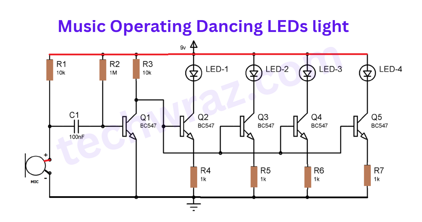
Music-Operating Dancing LED Lights circuit Diagram
Components Required
- Condenser Mic 1
- NPN Transistor BC547 5
- Resistances—10k (2), 1k (4), 1M (1)
- Ceramic Capacitor 100nF (1)
- LEDs (4)
- 9v Battery (1)
- Breadboard and connecting wires
Working Explanation of Music-Operating Dancing LEDs
The condenser mic picks up the sound signals and converts them into voltage levels in this simple LED music light circuit. These voltage signals are further fed to the R-C filter through R2 and C1), to eliminate the noise. Further, a BC547 transistor (Q1) is used to amplify the inputted signals from the R-C filter. Then these music signals are given to the array of four transistors (Q2, Q3, Q4, and Q5). In this circuit, the transistor works as an amplifier and runs four LEDs according to the sound style. This creates an interesting sequence of dancing LEDs. We can adjust the sensitivity of MIC by changing the value of R2 and C1 by using the formula for the R-C filter: F = 1/(2πRC).
Here, F is the cut-off frequency, which means only allow frequencies above F. It can be easily deduced that the more the value of RC, the less the cutofffrequency and the higher the sensitivity of MIC. And the higher the sensitivity of the circuit means MIC can pick low-volume sounds; hence, LEDs can glow on low also. So by adjusting its sensitivity, we can make it less reactive, reacting only on high-note beats, or we can also make it more sensitive to react on every little beat in the music. .We have set its sensitivity at a moderate level.
The condenser mic should be connected properly in the circuit, according to its polarity and sensitivity. To determine the polarity of MIC, you should look at the MIC terminal points; the terminal that has three soldering lines is a negative point.
The transistor BC547 is an NPN transistor, which is being used here as an amplifier. An NPN transistor acts as an open switch when no voltage is applied to its base (B), and it acts as a closed switch when there is some voltage at its base.
For more detail about these circuits, click