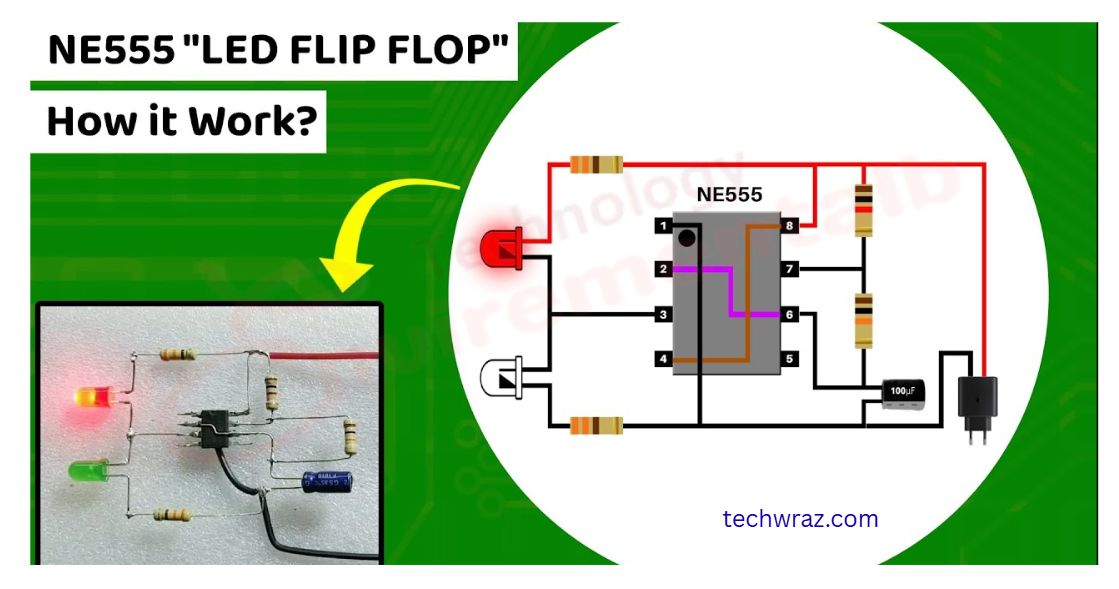
In this project I am going to show a very useful and beautiful flip flop circuit using timer IC 555. The circuit is able to blink 8 super bright blue and red LEDs. The circuit is built around a famous 555 timer IC, which is wired as an astable multivibrator here. The LEDs are classified in two pairs containing 8 LEDs. The number of LEDs can be increased and decreased according to your requirements and desire.
IC will blink each pair one by one or in a flip-flop manner. A 10K variable resistor is used to adjust the flashing speed.
This is a 4-volt circuit, and if you want to run more LEDs on 12 volts, then use 3 LEDs in a series. The circuit given below will increase your understanding. You can change this as you want.
Pin diagram and description of IC555
| Pin | Name | Purpose |
| 1 | GND | Ground reference voltage, low level (0 V) |
| 2 | TRIG | The OUT pin goes high, and a timing interval starts when this input falls below 1/2 of CTRL voltage (which is typically 1/3 Vcc, CTRL being 2/3 Vcc by default if CTRL is left open). In other words, OUT is high as long as the trigger is low. Output of the timer totally depends upon the amplitude of the external trigger voltage applied to this pin. |
| 3 | OUT | This output is driven to approximately 1.7 V below +Vcc, or to GND |
| 4 | RESET |
A timing interval may be reset by driving this input to GND, but the timing does not begin again until RESET rises above approximately 0.7 volts. Overrides TRIG, which overrides threshold.
|
| 5 | CTRL | Provides “control” access to the internal voltage divider (by default, 2/3 Vcc). |
| 6 | THR | The timing (OUT high) interval ends when the voltage at the threshold is greater than that at CTRL (2/3 Vcc if CTRL is open). |
| 7 | DIS | Open collector output, which may discharge a capacitor between intervals. In phase with output. |
| 8 | Vcc | Positive supply voltage, which is usually between 3 and 15 V depending on the variation. |
IMPORTANT | FEATURES OF IC 555
Almost in every circuit, the 555 ic is used today. For a 555 timer working as a flip-flop or as a multivibrator, it has a particular set of configurations. Some of the major features are as follows.
- Sinking or sourcing 200 mA of load current.
- It operates from a wide range of power ranging from +5 volts to +18 volts supply voltage.
- The output of a 555 timer can drive a transistor-transistor logic (TTL) due to its high current output.
- The external components should be selected properly so that the timing intervals can be made into several minutes along with the frequencies exceeding several hundred kilohertz.
- It has a temperature stability of 50 parts per million (ppm) per degree Celsius change in temperature, which is equivalent to 0.005%/°C.
- Also, the maximum power dissipation per package is 600 mW, and its trigger and reset inputs have logic compatibility.
- The duty cycle of the timer is adjustable.
You May Also Like
- Difference between BC547 and BC557 Transistor
- BC547 transistor pinout Datasheet
- C945 Transistor Pinout Datasheet
- Solar drone with wingspan wider than jumbo jet could fly for months
- Change the Direction of a DC Motor
- 12-volt battery level indicator
- An Introduction To Arduino
- The Future of Passwords: Are Biometrics and Passkeys the Solution?