PC817 optocouplers, also called photocouplers & optoisolators, are an IC kind of seeing tool available from 4 pins to many numbers of pins; they are commonly used for the separation of two circuits from each other. PC817 is a commonly used optocoupler; it contains one IR LED and one phototransistor in its package. Its working is easy: when a user applies voltage to the IR LED, which is connected to pins 1 and 2, the LED becomes activated and the light is received by the internal phototransistor; therefore, it is manufactured in a saturation state, due to which it connects pins 3 and 4 with each other. PC817 is an extensively used optocoupler and works well in an electronic circuit for a single task. If you need many isolation tasks at the same time, then you can also use other optocouplers that contain a couple of IR LEDs and phototransistors in one package. The pin configuration of a PC817 optocoupler.
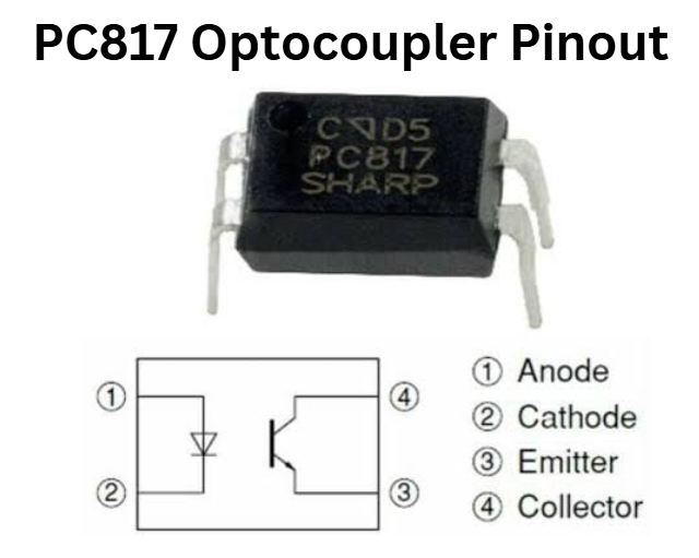
PC817 Optocoupler Pinout
The pinout detail of the optocoupler is given below in the picture with its circuit diagram.
PC817 optocoupler features:
- Package-Type: 4 Pin Dip and SMT
- Transistor Types of NPN
- Maximum Collector Current (IC): 50 mA
- Maximum Collector-Emitter Voltage (VCEO): 80V
- Collector-Emitter Saturation Voltage: 0.1 to 0.2
- Max Emitter-Collector Voltage (VEBO): Volt
- Max Collector Dissipation (Pc): 200 MW
- Maximum Storage and Operating temperature Should Be: -55 to +120 Centigrade for storage & -30 to +100 for operating
The equivalent of the PC817 optocoupler:
The replacement and equivalent of PC817 optocoupler are SFH615, AK817P, PC816, LTV123, TLP621, TLP321, TLP421, PC17K1, SFH615A, LTV-610, K1010, PS2501-1, PS2561-1, PS2571-1, LTV-816, LTV-817(-V), PC123, and H11A817.
Where TO Use PC817 Optocoupler:
If you are going to design an electronic circuit in which there is a chance of voltage spikes or voltage surges that may weaken or destroy the tools or the circuit, then you can use the PC817 optocoupler to separate the circuit. Furthermore, it can also be used to remove sound from an electronic signal and separate DC and low-voltage circuits from AC and high-voltage circuits. You can too use it where you want to control larger voltage or AC voltage from any small signal which can be a digital signal or the same.
How to Use the PC817 Optocoupler:
Using the PC817 optocoupler is very easy; there are four pins shown in the pinout details. Pin 1 is the anode, or positive pin, of the IR LED that should be coupled from the output signal of your circuit, and pin 2 should be coupled to the earth. The other portion of the circuit, which you want to separate or control, should be connected with the pin3 emitter and the pin4 collector. The pin3 and pin4 act the same as any other normal transistor for the ideal BJT transistor’s emitter and collector.
Applications of optocouplers:
- Office and home appliances
- Sensor Circuits
- The output of Microcontrollers to control devices
- Digital circuits
- Power supplies and chargers
- Isolation between any two type of circuits
How we can safely run long in a circuit:
To carefully run these tools in your circuit for the long run, it is recommended to always stay below the absolute max ratings. Do not drive a load above 50 mA. The iLED internal IR LED can be operated the same as you operate any other normal LED with a current-limiting resistor, so always use a current-limiting resistor at pin 1 of the optocoupler. Do not drive the tool in temperature below -30 centigrade or above 100 centigrade and always store in temperature above -55 centigrade and under 125 degrees centigrade.
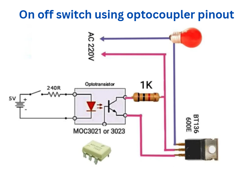
On off switch using optocoupler pinout wiring diagram
Related Posts
- AT24C32 IC Two-Wire Serial EEPROM
- CD4017 IC Pinout, Features, and applications
- LM35 Temperature Sensor pinout
- LM324 IC: Pin Configuration, Circuit working, Features and applications
- LM358 IC Pinout, Description, Equivalents
- LM741 Pin Configuration, Features & Working
- 555 Timer IC: PIN Diagram, Working, Features & Uses