In this project, we are going to design a single-transistor FM transmitter circuit that works effectively in a 1-2 km range. In this circuit, we have used an electret condenser microphone as an input source that gains signal in analog form. You can easily make this transmitter on a PCB or without a PCB because it consists of very few components. The coils and the antenna can be designed as a part of the PCB as an antenna if you make it on the PCB. If you want to increase the range of the transmitter, then you must install the long high antenna with any wire. To understand the working of this transmitter, we divide it into three main stages as follows.
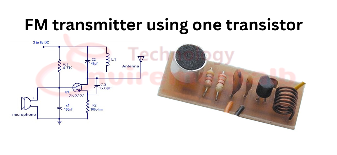
FM transmitter using one transistor Circuit Diagram
The circuit diagram of an FM transmitter using one transistor is given below, and we also discuss its total working with stages.
FM transmitter using one transistor components
The following components are required to make an FM transmitter circuit:
| S.No. | Component | Value | Qty |
|---|---|---|---|
| 1. | Ceramic Capacitor | 6.8 pF, 47 pF, 100 nF | 1, 1, 1 |
| 2. | Resistor | 4.7KΩ, 100Ω | 1, 1 |
| 3. | Battery | 3 to V | 1 |
| 4. | Transistor | 2n2222 | 1 |
| 5. | Inductor | 212 μH (5 turns of 15-gauge copper wire) | 1 |
| 6. | Micro-phone | – | 1 |
| 7. | Antenna | – | 1 |
Simple FM Transmitter stages
- Input stage
- Modulation Stage
- Output Stage
1. Input Stage state of Simple FM Transmitter
The input stage consists of capacitors C1 and C3, resistor R1, and a microphone. Input signals into the FM transmitter must not contain a DC component, as it would adversely affect the modulation stage, and therefore no FM signal would be generated. Therefore, the C3 capacitor is used to control the DC adverse. Resistor R1 (resistor) provides a small amount of current to the base of the transistor, so in this way the transistor remains on and the 1st stage is complete in this way.
2. Modulation Stage of Simple FM Transmitter
The oscillator/modulation stage consists of C2 (variable capacitor for adjusting frequency), C4, L1, and R2, with the frequency of oscillation being determined by C2 and L1 only. The modulation stage provides a carrier signal that is modulated by the input signals. Keep in mind that input signals are gained by the microphone or any input source. When we give power to a circuit, a rush of current flows through the L1 (inductor). This current passes through the capacitor C4 and due to this current flow through R2. R2 is connected with the emitter of the transistor, so the same voltage is present on the emitter. As a voltage increase on the emitter, it reduces In VBE reduces the condition of the transistor. When power is applied to the circuit, a rush of current flows through the inductor.
This rush of current will also pass through C4 via capacitive coupling, which will result in current flowing through R2. Current flowing through R2 will result in a voltage drop across R2, and since R2 is connected to the emitter of Q1, the same voltage will be present on the emitter of Q1. As C4 begins to charge, the small amount of current flow through C4 reduces, and in this way less current passes through R2 due to this increase in the size of VBe, and conduction increases. Due to an increase in conduction, C4 discharges, and the whole cycle starts to repeat again.
3. Output/Emitting Stage of FM Transmitter
The signals that are generated by the modulation stage are emitted through the long wire (antenna). How to Receive Fm transmitter signals The FM transmitter signals can be received through FM receivers such as simple FM radios, and in the present age, most smartphones also feature FM receivers. The single-transistor FM transmitter frequency can be searched through the FM receiver between 88 MHz. This frequency can be changed with the variable capacitor or expands the rings of inductor coil L1. The FM transmitter frequency should be adjusted on an empty area of searching; otherwise, it will disturb the frequency of a nearby tuned radio, which is not allowed by law.
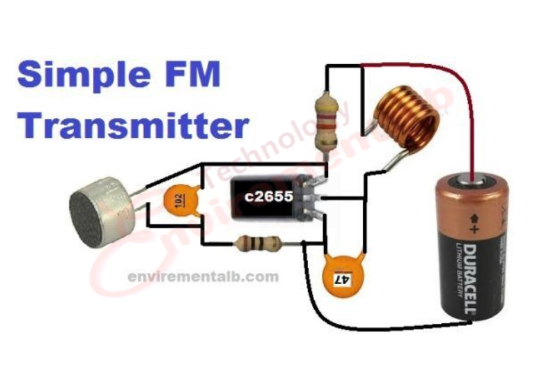
Components Required for This Transmitter
- Micro-phone
- Transistor 2n2222/2655c
- Inductor coil 5 turns with 16 No. copper wire
- pf 102 (100 nf)
- pf 47
- 100-ohm resistor
- 4.7k resistor
- 3 to 6 V battery