A small and simple AM radio project with only 2 transistors. Mediumwave stations can be listened to in your area through this circuit. The variable capacitor (VC1) in parallel with the coil (L1) acts as a tunable resonant circuit. This “tank” circuit can be adjusted at the desired AM frequency.
Components required for Simple AM Radio Receiver Circuit
The following components are required for this simple AM radio circuit. Frequency can be adjusted according to the component’s powers and formula. Detail about components is given below.
| Ref Des | Name | Value | Description |
|---|---|---|---|
| C1 | Capacitor | 0.1 µF | PF Capacitor |
| C2 | Capacitor | 470 pF | PF Capacitor |
| C3 | Capacitor | 10 µF | 25v |
| C4 | Capacitor | 10 µF | 25v |
| L1 | AIR CORE | 200 uH | Air core coil |
| Q1 | Transistor | 2n2222 | NPN |
| Q2 | Transistor | 2n2222 | NPN |
| R1 | Resistor | 1M | 1/4 watt |
| R2 | RESISTOR | 22k | 1/4 watt |
| R3 | RESISTOR | 4.7K | 1/4 watt |
| R4 | RESISTOR | 1K | 1/4 watt |
| VR1 | Variable Resistor | 4.7K | 4.7K to 10K |
| SP | Speaker | 8 Ohm | simple |
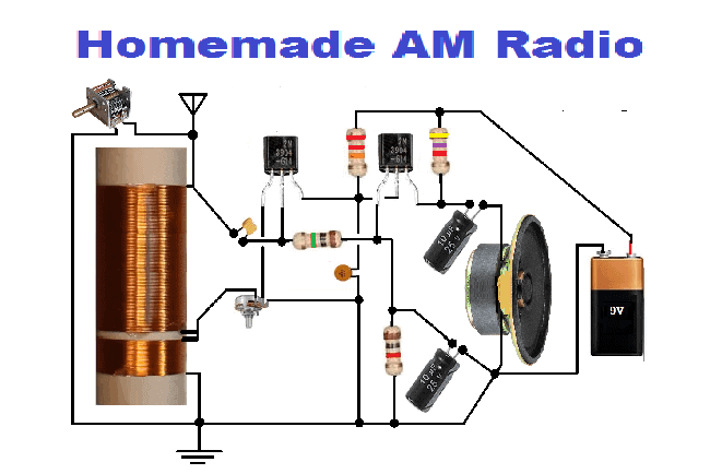
Circuit Diagram of Simple AM Radio Receiver
The circuit diagram of a simple and homemade AM radio circuit is given below with total detailed components.
RF component of Simple AM Radio Receiver Circuit
Modulated RF voltage developed through the tuned circuit is given to the transistor (Q1) 2n2222 through the coupling capacitor (C1) 0.2 uf. After feeding, Q1 amplifies modulated signals and demodulates the signal. In the collector terminal of Q1, the RF component is shorted to ground through the capacitor (C2) 470 pF.
Amplification of the Audio and regeneration
In the circuit, Q2 is separate for audio output. At the emitter of Q1 (NPN transistor), a portion of the signal is fed back to L1. The amount of this feedback is adjustable with a variable resistor (VR1). The speaker is connected to the collector of Q2 for the output of amplified signals through C4. The capacitor C3 is charged through Q2 and feeds Q1 through resistor (R1). The voltage through C3 is fed back as an automatic gain control to the base of Q1. This circuit can be used as a final project for electronics students. For more detail, please visit
Application of AM Radio
This AM radio circuit can be used for the following purposes.
- Electronics Fun
- Electronics beginner students
- To listen to AM broadcasting