In this post we are going to discuss a voltage multiplier circuit diagram with its full working. A voltage multiplier is an electronic circuit that converts AC voltage into high DC voltage by using diodes and capacitors. We can design this circuit with a transformer or without a transformer. Sometimes we need high DC voltages for our electronic appliances, and then this circuit is very useful. The voltage multiplier is also known as a voltage doubler, voltage tripler, and so on.

Voltage multiplier circuit diagram
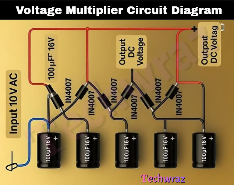
The working of a high-voltage multiplier circuit is very simple; we explain its working step by step. A DC or AC voltage multiplier circuit uses a series of capacitors and diodes to multiply the voltages. The arrangement of capacitors and diodes is shown above in the animated circuit diagram. We are also adding a circuit diagram to understand the structure of this circuit.
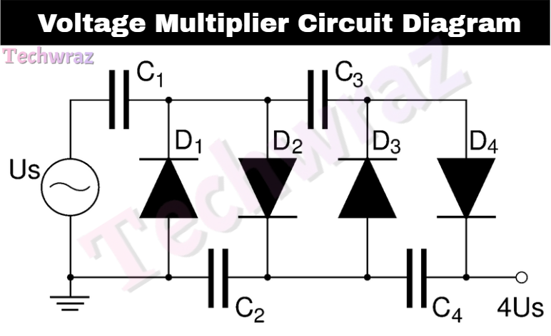
During the positive and negative cycles of AC input, capacitors charge through diodes and store energy, and the first capacitor charges to the next capacitor, and in this way, capacitors charge in series. The output voltage is typically a multiple like 2x, 3x, 4x, …x, and so on.
Operation or working
- During the positive half-cycle of the AC input, diodes allow current to flow in one direction; this will charge the first capacitor.
- During the negative half-cycle, the capacitors discharge through other diodes, adding their stored voltage to the next stage.
- Each stage adds approximately twice the peak AC voltage.
Voltage multiplier circuit diagram components
To design this circuit we need the following simple diodes, capacitors, AC input source, and load to check the output.
- Diodes: in4007
- Capacitors: 100 uF and 100 V, suitable to to bear high voltages
- AC Input: Transformer is best AC input source
- Load: You can run any low-power-consumption appliance or test on the meter.
You May Also Like
- Difference between BC547 and BC557 Transistor
- BC547 transistor pinout Datasheet
- C945 Transistor Pinout Datasheet
- Solar drone with wingspan wider than jumbo jet could fly for months
- Change the Direction of a DC Motor
- 12-volt battery level indicator
- An Introduction To Arduino
- The Future of Passwords: Are Biometrics and Passkeys the Solution?
- TLX9165T photorelay delivers 1500V protection