In this short post, we are going to explain the buck converter circuit. A buck converter is a type of DC-DC power converter that steps down a higher DC voltage to a lower DC voltage. It is commonly used in power supplies, LED drivers, battery chargers, and many electronic devices where efficient voltage regulation is needed.
Working of buck converter Circuit
A buck converter uses switching components such as a MOSFET, a transistor, a diode, an inductor, and a capacitor. The switch turns on and off at high frequency, controlling the energy delivered to the inductor. The inductor and capacitor smooth the pulsed voltage into a stable, lower DC output. The duty cycle, total switching ratio, and ON time determine the output voltage.
It is mostly used when we need a stable lower voltage from higher sources such as high-voltage solar panels and we need 24V, 12V, 9V, or 5V output for our appliances. It is 90% efficient or more.
Buck converter circuit Equation or formula
Vout=D×VinV_{out} = D \times V_{iV_{in}
where D = duty cycle (0 < D < 1).
Input voltage (Vin) > Output voltage (Vout)
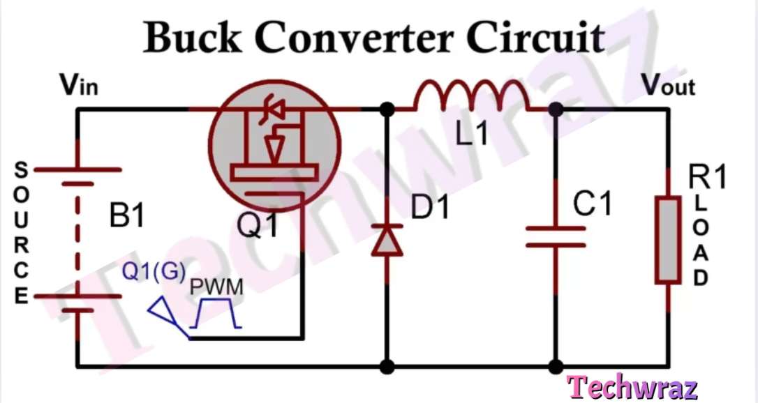
Buck Converter Circuit Diagram
Here is a simple circuit diagram of a buck converter.

Components Used In the above Circuit diagram
| Component | Description |
|---|---|
| B1 | DC power source such as battery, solar panel, or any DC power supply |
| Q1 | Power MOSFET switch to control the current flow |
| D1 | freewheeling diode |
| L1 | Inductor for energy storage and smoothing |
| C1 | Output capacitor for filtering the output voltages |
| R1 | Load |
Advantages of Buck Converter
Some advantages of the buck converter circuit are given below in the list.
- Typically 85–95% because power loss is minimal in switching devices.
- Requires smaller heat sinks and components compared to linear regulators.
- Output voltage can be finely tuned by changing the PWM duty cycle.
- Can handle a wide range of input/output voltage levels and currents.
- Unlike linear regulators, very little power is dissipated as heat.
Disadvantages of Buck Converter
- Requires careful design of switching frequency, control loop, and components.
- Inductors may be bulky for high-current applications.
- Requires a low forward voltage drop, fast-recovery, or Schottky diode.
- Output voltage contains ripple if not filtered properly.
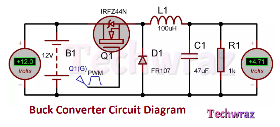
Final Circuit Diagram of Buck converter
Picture of a buck converter with open-loop control
You May Also Like
- Difference between BC547 and BC557 Transistor
- BC547 transistor pinout Datasheet
- C945 Transistor Pinout Datasheet
- Solar drone with wingspan wider than jumbo jet could fly for months
- Change the Direction of a DC Motor
- 12-volt battery level indicator
- An Introduction To Arduino
- The Future of Passwords: Are Biometrics and Passkeys the Solution?