This article is about the introduction and pin details of the ULN2003. The ULN2003 is an integrated circuit array used for driving high-current loads from low-level logic signals. It is widely used in electronics projects and control systems that involve relays, stepper motors, lamps, and other inductive loads. The 2003 consists of seven NPN Darlington pairs each pair is capable. Each pair handles up to 500 mA.
These pairs amplify small input currents from microcontrollers, such as Arduino or Raspberry Pi, into larger currents suitable for driving heavier loads.
Advantages of ULN2003 Integrated Circuit
The ULN2003 has many advantages. ULN2003 has built-in protection diodes, which safeguard the circuit against voltage spikes generated by inductive components.
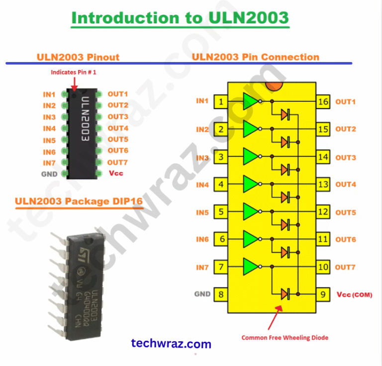
Pin Details of ULN2003
The ULN2003 is a 16-pin integrated circuit (IC) that contains seven Darlington transistor pairs. Each pair can drive an inductive or resistive load.
| Pin No. | Name | Description |
|---|---|---|
| 1 | Input 1 | Logic input for driver 1 (connect to microcontroller or logic circuit) |
| 2 | Input 2 | Logic input for driver 2 |
| 3 | Input 3 | Logic input for driver 3 |
| 4 | Input 4 | Logic input for driver 4 |
| 5 | Input 5 | Logic input for driver 5 |
| 6 | Input 6 | Logic input for driver 6 |
| 7 | Input 7 | Logic input for driver 7 |
| 8 | GND | Ground (connect to the system ground) |
| 9 | COM (Common) | Common freewheeling diode connection (connect to +V when driving inductive loads like motors or relays) |
| 10 | Output 7 | Output of driver 7 (connects to load) |
| 11 | Output 6 | Output of driver 6 |
| 12 | Output 5 | Output of driver 5 |
| 13 | Output 4 | Output of driver 4 |
| 14 | Output 3 | Output of driver 3 |
| 15 | Output 2 | Output of driver 2 |
| 16 | Output 1 | Output of driver 1 |
Working of ULN2003 IC
IC ULN2003 works as a relay driver or current amplifier, allowing low-power control signals from a microcontroller (like Arduino, PIC, or Raspberry Pi) to drive high-current loads such as relays, motors, solenoids, or lamps.
The ULN2003 is made up of seven Darlington transistor pairs. Each pair acts as a switch that can handle higher current and voltage than a single transistor. A Darlington pair means two NPN transistors connected in such a way that the current amplified by the first transistor is further amplified by the second. This provides a very high current gain, so even a small input current can control a large output current.
How It Works Step-by-Step
Input Signal
A logic signal, usually 5V or 3.3V, from the microcontroller is applied to one of the input pins from 1 to 7. When the input pin goes HIGH, it turns ON the corresponding Darlington transistor pair inside the IC.
Output Action
When the transistor pair turns ON, the corresponding output pin 10 to 16 is connected to ground. This allows current to flow from the external power supply, through the load, and into the ULN2003 to ground.
Load Operation
The load (motor, relay, lamp, etc.) is connected between the positive supply positive voltages and the output pin of the ULN2003. So, when the output goes LOW, current flows through the load, activating it.
Protection (COM Pin)
The COM pin (Pin 9) is connected to the positive supply positive voltages when driving inductive loads. It is internally connected to flyback diodes that protect the IC from voltage spikes (back EMF) generated when the inductive load is switched off.
Water Level Indicator Using IC
we can understand the working of IC uln2003 with the given circuit diagram in more deeply
You May Also Like
- Difference between BC547 and BC557 Transistor
- BC547 transistor pinout Datasheet
- C945 Transistor Pinout Datasheet
- Solar drone with wingspan wider than jumbo jet could fly for months
- Change the Direction of a DC Motor
- 12-volt battery level indicator
- An Introduction To Arduino
- The Future of Passwords: Are Biometrics and Passkeys the Solution?