In this post I am going to explain the boost converter circuit using the MC34063 IC. A boost converter raises (steps up) a lower DC voltage to a higher DC voltage using an inductor, a switching device, and an energy-storage capacitor. The MC34063 is a popular, inexpensive, single-chip switching regulator that contains an internal switching transistor, comparator, reference, oscillator, and current limit—so it’s convenient for building small boost (and buck/inverting) converters.
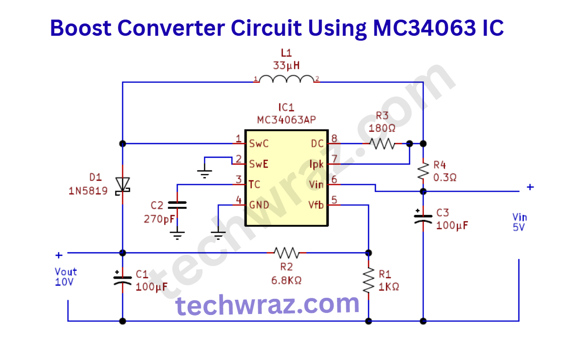
in this circuit, we designed a boost converter circuit. Using the MC34063 IC with a few external components, this IC is suitable for compact DC/DC boost converter circuits; it contains all the primary circuitry needed for building simple DC-DC converters. The following circuit is designed to boost input voltage from 5V to 10V using a single power supply source.
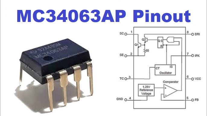
MC34063 Pinout
We are using MC34063AP in this circuit, so we must know about the pin detail of MC35063AP. This pin detail of IC is given below the diagram.
| MC34063 Pinout | ||
|---|---|---|
| Pin No. | Pin Name | |
| 1 | Switch Collector | |
| 2 | Switch Emitter | |
| 3 | Timing Capacitor | |
| 4 | Ground (GND) | |
| 5 | Comparator Inverting Input | |
| 6 | Voltage (Vcc) | |
| 7 | Ipk | |
| 8 | Driver Collector | |
Boost Converter Circuit Using MC34063 IC
The Circuit diagram of boost converter using MC34063 is given below
Hardware Components
The following components are required to make the boost converter circuit.
Applications of Boost converter
This boost converter circuit is most suitable to drive or bias output actuators in the microcontroller or microprocessor-based design.
| S.No. | Component | Value | Qty |
|---|---|---|---|
| 1. | IC | MC34063AP | 1 |
| 2. | Schottky diode | 1N5819 | 1 |
| 3. | Inductor | 33 µH | 1 |
| 4. | Electrolyte Capacitor | 100 µF | 2 |
| 5. | Resistor | 0.3Ω, 1KΩ, 6.8KΩ, 180Ω | 1, 1, 1, 1 |
| 6. | Ceramic Capacitor | 270 pF | 1 |
| 7. | Power Supply | 5V | 1 |
Working Explanation of Boost Converter Using MC34063 IC
The MC34063 IC is a versatile DC-DC converter chip that can work as a step-up (boost), step-down (buck), or inverting converter. In a boost converter, it increases the input voltage to a higher output voltage.
The working of the boost converter circuit using the MC34063 IC is based on energy storage in an inductor and controlled switching. When the internal transistor of the IC turns ON, current flows through the inductor, and energy is stored in its magnetic field. During this period, the diode prevents current from flowing to the output.
When the transistor turns OFF, the magnetic field in the inductor collapses, causing the inductor to release stored energy. This energy adds to the input voltage and flows through the diode to charge the output capacitor, providing a higher voltage at the output.
The IC uses an internal oscillator, comparator, and switch transistor to regulate the output voltage. The feedback network (resistors) monitors the output and adjusts the duty cycle to maintain a stable voltage.
Overall, the MC34063 efficiently boosts a lower DC voltage (e.g., 5V) to a higher one (e.g., 12V) with minimal external components like an inductor, diode, capacitor, and a few resistors.