The CD4017 IC is a CMOS decade counter. This IC is mostly used for low-range counting applications. It counts from 0 to 10 (the decade count). It can count from zero to ten (0-10), and its outputs are decoded. This IC takes less space and saves time to build our circuits when our application demands using a counter followed by a decoder IC. This IC also simplifies the design used in automotive industries, electronic industries, medical electronic devices, alarms, and electronic instrumentation devices.
Features of CD4017 IC
CD4017 has the following main features:
- The supply voltage of this IC is 3V to 15V DC, typically 5V.
- Supports 10 decoded outputs (0-9).
- Maximum Clock Frequency: 5.5 MHz.
- TTL (Transistor-Transistor Logic) compatible.
- Available in 16-pin PDIP, GDIP, and PDSO packages.
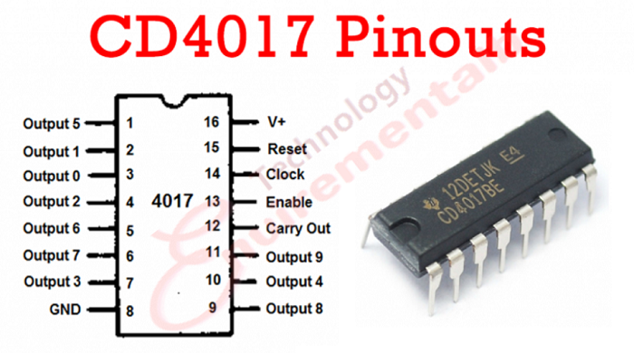
CD4017 pinout
The pin detail of the IC CD4017 with detail is given below.

- Pins 1 to 7 and 9 to 11 are output pins.
- These pins change to ‘high’ level one by one according to the output sequence. For each clock signal, each pin goes high.
Clock Inhibit/Enable pin (Pin 13)
- The EN pin (Enable Pin) enables the CD 4017 IC. It enables the IC when the pin is active low.
- In order to switch off the IC, the EN pin should be connected to the active high input. When this pin is active high, it stops the clock signals.
Clock pin (pin 14)
- The clock pin provides signals to the IC for sequential output.
- When the first clock pulse is applied on the clock pin, then pin 5 goes high (its output is 0).
- The clock input pin only responds to the positive voltage signal or positive clock.
Reset pin (Pin 15)
- Reset pin resets the output of the sequence, so output goes on pin 3 as it’s reset.
- Reset pin (pin 15) should be connected to ground in order to reset the circuit.
Ground pin & supply pin (Pin 8 & Pin 16)
Pin number 8 is the ground pin, and it is connected to negative supply voltage, while pin 16 is the supply pin for the CD4017 integrated circuit, and it is connected to a positive voltage supply of 3v to 16v.
IC 4017 internal circuit
The internal circuit of the 4017 IC is shown below in the picture.
CD4017 IC using waveforms
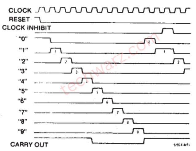
This is the timing diagram of the CD4017 IC that shows us the comparison and also explains the counting sequence of the outputs (Q0-Q9) shifting from one pin to the next pin in sequence.
Application of decade counter ic CD4017
Here are some circuits where CD4017 IC is commonly used
- 3X3 LED cube circuit
- Police lights circuit
- Clap on and off switch circuit
- Unbiased digital dice circuit
- Automatic washroom lights control
- Adjustable Timer circuit
- LED Running Light
Price of CD4017 IC
The price of this IC is approximately $0.2 to $0.3 according to country.
cd4017 datasheet
The datasheet of cd4017 is Click
LED chaser by using CD4017 IC
In the video given below, we have made a simple LED chaser by using a 4017 IC. This is very simple and easy to make a project for beginners, and this project also explains the working of this IC very easily.