An electronic device that can be turned on and off by a clap is called a clap switch. It can control light appliances by users’ clapping action also. It was invented by Stevens, R. Carlile, and E. Dale Reamer in 1996. The main advantage of this circuit or device is that it is mainly helpful for a mobility-impaired person. The condenser mic is one of the main parts of the circuit that takes input clap sound based on the pitch of the clap. This article gives an overview of the clap switch. Electrical pulses are the desired input to the clap switch circuit.
What is Clap Switch
Definition: A clap switch is an electronic circuit or device that controls electrical appliances like tube lights, energy savers, LED bulbs, etc. with user clapping action. It is mainly useful for a person who cannot move from one place to another for switching on or off electrical or electronic appliances. Clap switch circuits can be designed in a variety of ways. Nowadays electronics students are designing this circuit by using the decade counter IC 4017.
Circuit switch Circuit Diagram
This is a very simple circuit; you can change its design according to your requirements.
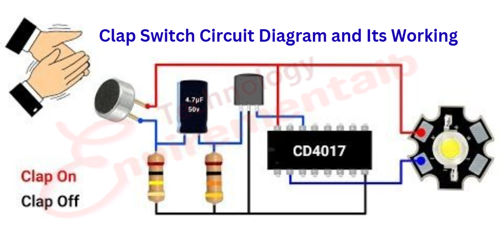
PART LIST For Clap switch circuit
- Prototyping board (roughly 1″ by 1″) or breadboard.
- 9v connector
- BC 547 transistor (npn)
- BC 557 Transistor (pnp)
- IC 4017
- 22k resistor
- 470 ohm resistor
- 1k resistor
- 6v relay
- 9v battery
Advantages
The following are the advantages of clap switch:
- It is reliable and low-cost circuit
- It is an advantageous technology for mobility-impaired persons.
- Automatically controls lights within a specified range by clapping action
- It provides good output efficiency and can control high load.
Disadvantages
The following are the disadvantages of a clap switch:
- The filter should be added in the circuit compulsorily for working.
- It is cumbersome compared to a traditional control switch, and it can be operated even by an unknown person.
Applications
The following are the applications of a clap switch:
- to on or off LED light
- Air conditioners
- Tv
- Motor, etc.
FAQs
1). Who invented the clap switch?
The main founder of this idea and circuit was R. Carlile Stevens.
2) When it was invented
The first clap switch circuit was invented in Feb 1996
3). Name two main applications of the Clap Switch.
The two main applications are
- LED light
- Fans
4). Is the Clapper a fire hazard?
No, the Clapper is not a fire hazard; it’s safe.
5). What is the main principle of a clap switch?
A clap switch converts sound energy into electrical pulses as input to the circuit and provides an output in order to control light appliances.
6). Can it work by all persons’ claps?
Yes, normally it can operate by the claps of all persons, but you can specify its working, like it will work with 2 or 3 claps or be turned off by 2 or more than 2 claps.
You May Also Like
- Difference between BC547 and BC557 Transistor
- BC547 transistor pinout Datasheet
- C945 Transistor Pinout Datasheet
- Solar drone with wingspan wider than jumbo jet could fly for months
- Change the Direction of a DC Motor
- 12-volt battery level indicator
- An Introduction To Arduino
- The Future of Passwords: Are Biometrics and Passkeys the Solution?