In this article, we are going to teach you how to make an LED chaser using the CD4017 IC easily with few components. This project is so easy even an inexperienced person can make it very easily. Many projects are available on the internet naming the LED chaser circuit using 4017 and 555. But in this project, we have clarified how you can make an LED chaser.
In the diagram given above, we have drawn a complete sketch of an LED chaser with only a 4017 IC.
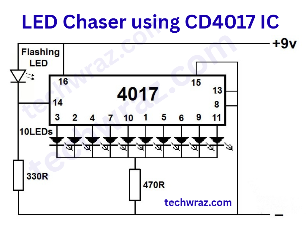
LED Chaser using CD4017 IC Circuit Diagram
4017IC pins Detail
Here is the pin detail of IC 4017 decade counter i.
Components Required
- LEDs – 11 any color
- Multicolor LED 5 mm
- 470-ohm resistor
- 330-ohm resistor
- IC 4017
- PCB or Breadboard
- 9v battery or power supply
Working of Circuit
CD4017, 74HC4017, or HCF4017BE is a 16-pin CMOS decade counter IC with 10 decoded outputs. The LED chaser with only 4017 IC is based on this IC. The CD 4017 ic is also called the ‘Johnson 10-stage decade counter.’ It gives output signals one by one in the form of a sequence when a clock signal from the clock input (pin 14) is given. When the 1st clock input is given, it gives output on pin no. 3 (output 0), and as clock 2 is given, it gives output 1 on pin no. 2, and so on.
Reset pin (pin 15) is used to reset the ic to zero—it is used to reset the counter to zero. The function of this pin (reset pin) reverts the sequence back to the initial state (zero states).
In this circuit a 3-color LED is used to give the pulse on point no. 14 (clock point). If you want to give a pulse from any other source, like from a timer IC or from a flip-flop circuit, you can do so easily. We use 555 IC normally to trigger 4017. But in this LED chaser circuit with only 4017 projects, we have used a tri-color LED for triggering.
Video Detail of these projects
If you want to watch the working of this project, please click here. In this video, we have made the project for a more clearly inefficient way. By following this video, everybody can make this project at home.