This is a simple and small Two Transistors FM transmitter. It is ideal for ready espionage for the strip from radio FM or a receiver of VHF. Of course, the recreational purpose also exists, and the children will adore having a transmitter that allows speaking for an FM radio placed at a distant place and, like this, pretending to be a secret agent.
Operation of the Two-Transistor FM Transmitter
The voice/music captured by the electric microphone, your voice, or close people’s chats is mischievous to the base of the PNP transistor Q1 through C1 (10 uF), where it is amplified. The resistor R2 together with R3 determines this amplification.
After having been amplified, the signal is removed from the collector of the Q1 transistor and mischievously sent to the base of the Q2 transistor (NPN), where it modulates in frequency the signal generated by this stage. This stage is an oscillator of high frequency that operates in the strip of FM. Your frequency is determined by L1 (0.3 uH) and the adjustment on the variable capacitor (CV).
The obtained signs, already modulated in frequency, are mischievous to a linked antenna in the collector of the transistor Q2 (BC557 Transistor).
The range of the transmitter depends on this antenna, on the feeding of the circuit, and on the place where it is operating. In the open field, with a 6 V battery and an antenna of about 40 cm of length, the range of this Two Transistor FM Transmitter can be 1000 meters. With a smaller antenna, the range of this transistor will reduce. A common wall is not an obstacle for this transmitter.
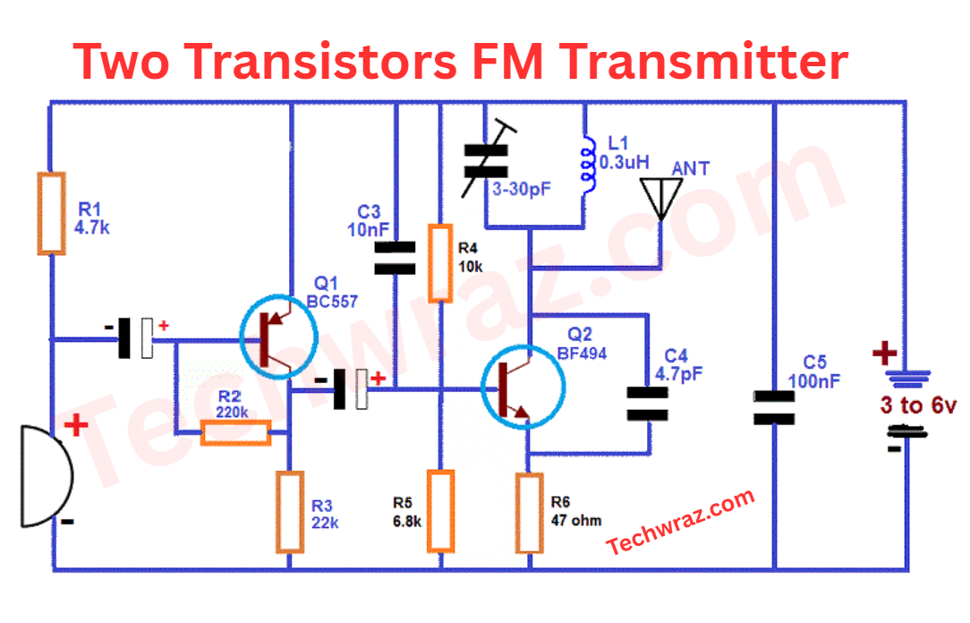
Circuit Diagram Two Transistors FM Transmitter
Components: Two Transistor FM Transmitter
Transistors:
Q1 – BC557
Q2 – BF494
MIC—microphone electret two terminals
Resistors: (1/4 W, 5%)
R1–4.7 KΩ
R2–220 KΩ
R3–22 KΩ
R4–10 KΩ
R5–6, 8 KΩ
R6–47 Ω
Capacitors:
C1–10 µF/16 V – ELECTROLYTIC
C2–4.7 µF/16 V – ELECTROLYTIC
C3–10 nF – ceramic
C4–4.7 pF – ceramic
C5–100 nF – ceramic
CV-trimmer from 3.30 to 5.50 pF
Other Parts:
L1 – 0.3 uH
B1 –3 to 9 V
ANT – antenna
Printed Circuit Board With Full Detail is given Below
For a full discussion about this circuit, you can freely discuss.
Thanks a lot
Related Article: Best Bluetooth FM Transmitter for Car