The water level indicator is a system that gets information about the water level in tanks, which is used in homes and public places. We can control the overflow of water tanks by using the tank level indicator. As everybody knows, when the water is stored in the tank, nobody can identify the actual level of water in the water tank. That is mostly water tank overflow, and it’s a great loss of water as well as electricity.
In this simple water level indicator project, we have used a switching IC ULN 2003 to indicate the water in the tank. Nowadays many projects on water indicators are available such as slope indicator water level meter, Digital water level indicators, water indicators using transistors, water level indicator alarms, etc.
Water Level Indicator Using IC ULN 2003
In this circuit, we are using the switching IC ULN 2003, a commonly used switching IC. Components used in these project areas:
- ULN2003 is a high-current and high-voltage Darlington array IC. It consists of seven open collector Darlington pairs with common emitters. A Darlington pair is an arrangement of two bipolar transistors. It is a relay driver IC. other types of similar ICs are the high-side toggle switch, low-side toggle switch, Darlington transistor, bipolar NPN transistor, N-channel MOSFET, ULN2003 driver IC, etc.
- LEDs: This IC has 7 output pins; that is why we are going to use 7 LEDs as water level indicators in the tank. These LEDs will glow according to the level of water in the tank.
- Battery: A DC supply of 9V is given through a battery to power up the circuit, or you can use a 9 to 12V DC supply as power.
- Resistors: 220-ohm resistors are used in this circuit to protect the LEDs because we are using a 9-volt to 12-volt power supply.
Circuit Diagram of final projects
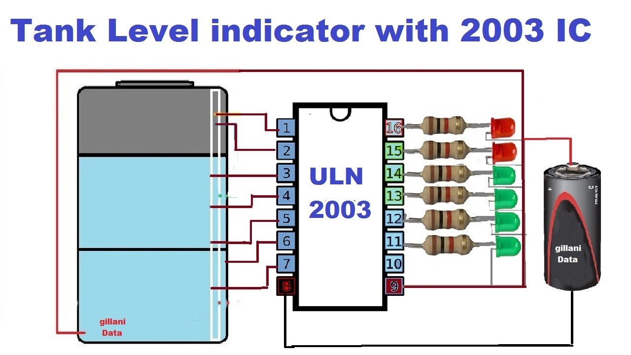
In the following animated circuit diagram, we have cleared all components with their connections. You can use long wires according to the distance of your tank to the electric board.
Water Level Indicator Using Alarm
We can also use an alarm with this circuit. It will alert you that now the tank is full and you should turn off the water pump.
Tank Level Indicator Auto Powered off
We can also use a cutoff relay with this circuit. When the tank is full, the relay will cut off the power automatically.
In this circuit given above, we have cleared all connections with auto cut-off water pump. When the tank is full, the water pump will auto-turn off because a relay is connected with the 7th output of the IC.
ULN2003 Pin Description
|
Pin No
|
Functions of all Pins
|
PINs
|
|
1
|
Input for 1st channel (enventalb.c
|
Input 1
|
|
2
|
Input for 2nd channel
|
Input 2
|
|
3
|
Input for 3rd channel
|
Input 3
|
|
4
|
Input for 4th channel
|
Input 4
|
|
5
|
Input for 5th channel
|
Input 5
|
|
6
|
Input for 6th channel
|
Input 6
|
|
7
|
Input for 7th channel
|
Input 7
|
|
8
|
Ground (0V)
|
Ground
|
|
9
|
Common freewheeling diodes
|
Common
|
|
10
|
Output for 7th channel
|
Output 7
|
|
11
|
Output for 6th channel
|
Output 6
|
|
12
|
Output for 5th channel
|
Output 5
|
|
13
|
Output for 4th channel
|
Output 4
|
|
14
|
Output for 3rd channel
|
Output 3
|
|
15
|
Output for 2nd channel
|
Output 2
|
|
16
|
Output for 1st channel
|
Output 1
|
Thanks for visiting our post. If you want to ask any question about the electronics projects, you can freely ask
You May Also Like
- Difference between BC547 and BC557 Transistor
- BC547 transistor pinout Datasheet
- C945 Transistor Pinout Datasheet
- Solar drone with wingspan wider than jumbo jet could fly for months
- Change the Direction of a DC Motor
- 12-volt battery level indicator
- An Introduction To Arduino
- The Future of Passwords: Are Biometrics and Passkeys the Solution?