A logic gate is a circuit that has one or more input voltages but only one output voltage.
Logic gates are basic building blocks of the digital system. OR, NOT, and AND gates are the fundamental kinds of gates. The interrelationship of gates to perform a type of logical work is called logic design.
Pin diagram of logic gates.
Types of Logic Gates:
- NOT GATE
- OR GATE
- AND GATE
- NOR GATE
- NAND GATE
NOT GATE:
A NOT gate creates an output that is the fulfillment of the input, and it has only one input signal.
It creates a 1 output when the input is 0. and
It creates a 0 output when the input is 1.
The four generally used methods of displaying the NOT operation as shown in the figure.
| In the English language | (Output Y is the complement of Input A) | ||||||
| Boolean expression | Y=Ā (“-” indicates NOT symbol) | ||||||
| symbol | |||||||
| truth table |
|
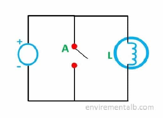
The diagram shows the idea of the NOT gate using a switch. The lamp (Y) will glow when the switch (A) is on. The lamp (Y) will not glow when the switch (A) is off.
 Logic Gates
The two possible switch positions are shown below. The truth table shows the NOT gate of the switch and lamp circuit. The output of the NOT gate circuit will be enabled when the input switch is ON.
| Input A | Output Y |
| Closed | Off |
| Open | On |
OR GATE:
An OR gate is infrequently called the “all gate.” An OR gate has two or more additional input signals.
- It creates a 1 output if any or all inputs are 1.
- It creates a 0 output when all inputs are 0.
An OR gate is similar to the action of parallel switches for the input.
The below table shows the four generally used methods for expressing the OR operation.
| In the English language | Inputs (A is ORed with B) to yield output Y | |||||||||||||||
| Boolean expression | A + B = Y (‘+’ Indicates OR symbol) | |||||||||||||||
| symbol |  |
|||||||||||||||
| truth table |
|
The diagram shows the idea of the OR gates using switches.
- The lamp (Y) will glow when either switch A, switch B, or switch C is closed.
- The lamp will also glow when switches A, B, and C are closed.
- The lamp will not glow when switches A, B, and C are open.
AND GATE:
An AND gate is infrequently called the “all or nothing gate.” It has two or more additional input signals.
- It creates a 1 output only when all inputs are 1. Otherwise,
- It creates a 0 output (nothing).
- In other words, it creates a 0 output when any input is 0.
The table below shows the four commonly used methods for expressing the AND operation.
| In the English language | Inputs (A is ANDed with B) to yield output Y | |||||||||||||||
| Boolean expression | A.B = Y (‘.’ Indicates AND symbol) | |||||||||||||||
| Symbol |  |
|||||||||||||||
| Truth table |
|
It shows the example of the AND gate using switches.
The lamp (Y) will glow only when both input switches (A and B) are off.
All other possible groups for switches A and B are shown in the below table.
Switch Combination:
| Input switches | Output Light | |
| A | B | Y |
| 1 | 1 | Off |
| 1 | 0 | Off |
| 0 | 1 | Off |
| 0 | 0 | On |
NOR GATE:
“A NOR gate shows an OR gate followed by an inverter.” A NOR gate has two or more input signals.
- It creates a 1 when all the inputs are 0.
- It creates a 0 output when any or all of the inputs are 1.
- It also works as a negative (bubbled) AND gate.
The table of the four generally used methods for expressing the NAND operation is given below.
| In the English language | Inputs (A is NORed with B) to yield output Y | |||||||||||||||
| Boolean expression | A + B = Y (‘+’ Indicates OR symbol) | |||||||||||||||
| Symbol | |
|||||||||||||||
| Truth table |
|
NAND GATE:
(“A NAND gate is a current AND gate followed by an inverter.”) A NAND gate has two or more input signals.
- It creates a 0 output only when all the inputs are 1.
- It creates a 1 output when any of the inputs is 0.
De Morgan’s second theorem says that the NAND function is equivalent to a negative (bubbled) OR gate.
The table the four generally used methods for expressing the NAND operation is given below
| In the English language | Inputs (A is Nanded with B) to yield output Y | |||||||||||||||
| Boolean expression | ||||||||||||||||
| Symbol | ||||||||||||||||
| Truth table |
|